-
北京左克科技有限公司
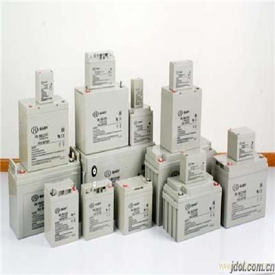
主营:铅酸蓄电池,ups电源,通信电源

北京左克科技有限公司
主营:铅酸蓄电池,ups电源,通信电源 14
14
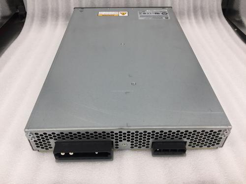
艾默生NetSure701 A41嵌入式电源-艾默生48V200A开关电源
艾默生NetSure701A41
艾默生NetSure701A41嵌入式高频开关电源系统是艾默生网络能源集多年开发和网上运行经验,为满足3G、FTTx、数据通信设备、传输设备和接入设备等网络建设需求而设计的高可靠、高功率密度、高性能、全数字化的插框式通信电源系统。该系统可兼容艾默生多种高频开关电源模块,同时具有节能休眠、高效混插等功能,系统配置交流侧、直流侧和信号侧等*防雷保护措施,尤其适合户外基站柜、户外机房等通信设备供电。
l 户外基站柜、宏站供电
l 3G室内覆盖供电
l 宽带综合接入供电
艾默生NetSure701A41
l 19英寸标准结构设计,具有优良的通用性
l 体积小,嵌入式安装,节省机房面积和安装成本
l 支持上、左、右进出线,更强适应性和节省用户空间
l *的防雷保护设计,可配套户外机柜使用
l 具有节能休眠功能,提高系统使用效率
l 支持高效-普通模块混插功能,更加环保
l 输入电压范围宽(80~300Vac),电网适应能力强
l 整流模块工作温度范围:-40~+75℃,环境适应能力强
l 整流模块采用数字化DSP控制技术,功率密度高达14 W/In3以上
l 无损伤热插拔,支持在线维护,方便快捷
l 完善的蓄电池管理功能,有效延长蓄电池的使用寿命
l 提供RS232、网口、干接点等多种通信接口,组网灵活,可实现远程监控
NetSure701 A41-S3艾默生电源。NetSure701 A41艾默生嵌入式通信电源有NetSure701 A41-S3 和 NetSure701 A41-S5 两种型号
艾默生NetSure701A41
系统容量:250A
监控模块:M221S/M222S
整流模块:5×R48-2900U/R48-3200e
交流配电
输入:1×125A/2P
输出:1×16A/1P
电池接入:2×125A/1P
直流配电
BLVD:2×32A/1P,2×16A/1P
LLVD:2×63A/1P,4×32A/1P
防雷:系统交流侧配置C级防雷,并具有直流侧,信号侧防雷
干接点:3路开关量输入,4路开关量告警输出
选配件:顶盖、温度传感器、电池架、直流配电扩展插框
艾默生NetSure701A41
普通模块:R48-2900U、R48-3200
高效模块:R48-3200e、R48-3500e、R48-4000e
电气参数
输入电压范围:80Vac~300Vac
功率因数:0.99
效率:普通>92%,高效>96%
输出电压范围:-42Vdc~-58Vdc
标称电压:-48Vdc
额定电压:-53.5Vdc
艾默生NetSure701A41
l M221S:LCD液晶显示,带网口,RS232
l M222S:LCD液晶显示,无网口,RS232
l 告警功能:
l 监控单元能对系统故障进行声光报警,同时能上报到后台主机
l 历史告警记录可存储200条,并具有按键操作记录功能
l 3路开关量输入;4路开关量告警输出,可扩展至8路开关量告警输出
l 告警的声音、时间可控
l 电池管理功能:
l 自动均浮充,智能充电限流管理,电池保护
l 放电测试,10组电池测试记录
l 三种充电方式:定时、快速、恒流
l 控制功能:
l 整流模块开关机,整流模块限流、均流、调压
l 电池组均充/浮充/测试转换,电池保护
l 四遥功能:
l 遥信、遥控、遥测、遥调
l 节能功能(选配):
l 模块自动休眠功能
l 高效-普通模块混插功能
艾默生NetSure701A41
结构:19英寸宽,6U高
尺寸(mm):483(宽)×360(深)×267(高)
重量(Kg):25(不包括整流模块和监控模块)
艾默生NetSure701 A41嵌入式电源-艾默生48V200A开关电源
English translation installation:
Pay attention to
1. It is forbidden to pack the rectifier module and the monitoring module into the power supply system, and then pack and transport it in a whole machine way, otherwise the equipment will be damaged.
2. Products factory, ac/dc power distribution box, rectifier module and monitoring module is separated for packaging and transport, unpacking at the user's site after the assembly, please keep good packaging material, so that when the next transport use.
Installation requirements
Before installing the power system, meet the environmental requirements, power supply requirements and safety protection requirements. Details are as follows:
7.1.1 environmental requirements.
When selecting power system installation site, the following environmental conditions should be considered:
1, the ambient temperature: it is recommended that range - 5 ℃ to 40 ℃
2. Altitude: the recommended range is less than 200 m.
3. Humidity: the recommended range is less than 90% RH, no condensation.
4. Vibration: the recommended range is less than 1.5m/s.
5. Dust degree: the recommended range is less than 1mg/m.
Insects, pests, pests, and termites: no.
7. Daylight: no direct exposure is recommended.
8. Mould: none
9. Corrosive substances: no pollutants such as salt, acid and smoke, etc.
When the power system works, the main heating part is the rectifier module. The rectification module has a fan built in, and its exhaust and ventilation path are in front of the wind, behind the wind. In order to ensure the ventilation before and after the power supply system, the free space above 40mm should be left in the front and rear of the power supply system.
7.1.2 power supply requirements.
Ac power supply should be used as the main power supply, using single-phase three-wire system. Reliable grounding of ground wire should be ensured in use. The ac power line should adopt copper core line, the line section area should be adjusted with the load. Use stable ac power supply as far as possible. The unstable ac power supply will affect the work of the power system and reduce its life.
7.1.3 safety protection requirements.
The rectification module is equipped with a lightning protection protector, which can withstand the shock wave of 1.2/50 mu s 6kV and 8/20 mu s 3kA lightning. In order to prevent the direct lightning overvoltage from entering the damaged rectifier module, the c-level and b-class lightning arresters should be installed in accordance with the relevant specifications before the ac municipal power is introduced into the power supply system.
7.2 installation
Installation steps of power system: install the ac/dc power distribution box first, then install the rectification module and monitoring module.
Installation steps of the ac/dc distribution box:
1. Remove the dc distribution box from the packing box.
2. The interface of the ac/dc power distribution frame is turned out, and it is inserted into the cabinet that is compatible with it.
3. Screw the screw into the four fixed screw holes shown in FIG. 2-1 with the phillips screwdriver.
7.2.2 install the rectification module.
Pay attention to
1. The rectification module has the function of hot plugging. Do not force too much in the insertion process to avoid damage to the rectifier module.
2. Non-professional maintenance personnel cannot plug or replace the rectification module.
3. When the number of rectification modules is less than 2, it should be installed in the order from left to right, and the remaining space is installed with the complete flow module fake panel.
Installation steps of rectification module:
1. Remove the rectification module from the packing box.
2. Hold the handle on the front panel of the rectifier module (see figure 2-2), and place the rectification module in the slot shown in figure 2-1.
3. The rectification module is slowly pushed to the front panel of the rectification module and the ac/dc power distribution panel.
4. Fixed screw on the front panel of the fixed rectifier module (see figure 2-2). The rectification module is locked on the ac/dc power distribution frame.
When disassembling, just loosen the fixed screw on the front panel of the rectification module and hold the handle to pull out the rectification module.
2.2.3 install monitoring module.
Pay attention to
1. The monitoring module has hot plug function. Do not force too much in the insertion process, so as not to damage the monitoring module.
2. Non-professional maintenance personnel cannot plug or replace the monitoring module.
Monitoring module installation steps:
1. Remove monitoring module from packing box.
2. Hold the handle on the front panel of the monitoring module (see figure 2-3), and place the monitoring module in the slot shown in figure 2-1.
3. The monitoring module is slowly pushed to the front panel of the monitoring module and the ac/dc power distribution panel.
4. Fixed screw on the front panel of the fixed monitoring module (see figure 2-3), and the monitoring module is locked on the ac/dc power distribution frame.
When disassembling, simply loosen the fixing screw on the front panel of the monitor module and pull the handle outward to pull out the monitoring module.
7.3 electrical installation
Pay attention to
Trained professionals must be responsible for wiring the power system.
The power system is the front-line system, and all the electrical connections are completed in front of the power system.
7.3.1 connect the power line.
Pay attention to
Attention should be paid before wiring:
1. Ensure that the ac input cable has no power, otherwise there is a risk of electric shock.
2. Ensure all switches on the ac/dc power distribution frame are placed in the off position (to the lower).
The power lines connected to the power system by the connection terminals on the ac/dc power distribution connectors include: ac input cable, battery cable and load cable. The fixing of each terminal.
The meaning is shown in figure 2-4.
Pay attention to
1. Ac input cable is a high-voltage working line. Make sure that the ac input power is switched off before wiring, and temporary ban sign is added to the switch that is forbidden.
2. Since there is no protection switch and fuse in the ac input of the power system, it is necessary to configure the power system at the front end of the ac input to be greater than 20A (240Vac).
Double pole empty or fuse for reliable electrical protection.
3. It is necessary to insulate the terminals of ac lines and other unneeded nudity.
As shown in FIG. 2-4, the ac input socket is located at the left of the dc power distribution frame and is the standard 3-core power outlet, so as long as the standard ac cable plug is met.
Insert the socket. The specifications and models of the cable can be selected according to the actual load. The cable model recommended for full configuration is shown in table 2-2.
The recommended cable model is recommended for full configuration.
Connecting line: ac input cable (2 rectification modules), maximum battery: 10A, recommended cable (AWG):16;
Connecting line: protective grounding wire, maximum battery: 10A, recommended cable (AWG):16;
Connect the dc cable.
1. Please check the polarity of the battery before connecting the battery.
2. If the battery, insert is connected to the ac/dc power distribution box the in box will issue a warning buzzer sounds to alert users to access the battery polarity error, the user should be timely change connection relationship!
3. The power system is electrically charged to increase the load, and strict tools and human insulation measures should be adopted to prevent short circuit during operation.
As shown below, the dc wiring terminal of the power supply system is located on the right side of the ac/dc distribution frame. The following table shows the screen printing of dc terminals.
Terminal identification: LOAD1; Meaning: load 1 terminal; Fuse specification: 10A, 0215010.M; Note: the pins marked "+" and "-" are respectively "48V+" and "48V-".
Terminal identification: LOAD2; Meaning: load 2 terminals; Fuse specification: 20A, 0314020.M; Note: the pins marked "+" and "-" are respectively "48V+" and "48V-".
Terminal identification: BATT; Meaning: battery terminals; Fuse specification: 20A, 0314020.M; Note: the pins marked "+" and "-" are respectively "48V+" and "48V-".
The specifications of the dc terminals are shown in the following table:
Terminal id number A single pin terminal 30 ℃ maximum current (A) @ recommended cables (AWG) corresponding to the branch control fuse capacity (A)
1. Terminal identification: LOAD1; Number of terminals 1; Maximum current of single pin (A) : 10A, recommended cable (AWG) : 18 ~ 16; Corresponding branch control fuse quantity (A) : 10A.
2. Terminal identification: LOAD2; Number of terminals 1; Maximum current of single pin (A) : 10A, recommended cable (AWG) : 18 ~ 16; Corresponding branch control fuse quantity (A) : 10A.
3. Terminal identification: BATT; Number of terminals 1; Maximum current of single pin (A) : 10A, recommended cable (AWG) : 18 ~ 16; Corresponding branch control fuse quantity (A) : 10A.
Note:
1. The actual load flow of each branch should not exceed its corresponding control fuse capacity.
2. When the power system working environment temperature below 40 ℃, derating to fuse using current rating of 95%; When the power supply system working environment temperature is higher than 30 ℃, the fuse should use current per 10 ℃ and derating 5% rise in use
1. Connected load cable
The specifications of the load cable shall be selected according to the size of each load, and the wiring shall conform to the engineering design requirements. The connection steps are as follows:
1) according to the polarity mark of the load terminal (see figure 2-4), the supporting cable is made. (the recommended positive pole is black and the negative pole is blue).
2) confirm that the power system has no power.
3) insert the load cable plug into the corresponding load terminal.
2. Connecting battery cable
The specifications of the battery cable should be selected according to the battery capacity, and the wiring should meet the engineering design requirements. The connection steps are as follows:
1) according to the polarity mark of the battery terminal (see figure 2-4), the supporting battery cable (recommended positive electrode with black, negative pole in blue).
2) confirm that the battery polarity is correct, and confirm that the power system has no power.
3) insert the battery cable plug into the corresponding battery terminal.
2.3.2 connect the ** line.
The ** interface of the power system is located on the front panel of the monitoring module.
Pay attention to
1. Communication cables must be shielded.
2. In order to achieve better EMC effect, it is suggested to set up a magnetic ring (NiZn material) at both ends of the communication cable. Magnetic conductivity 1000/2000 series; Anti-high frequency noise interference.
Communication port RS232/RS485 main port and communication port RS232/RS485 standby.
The main mouth is the same as the backup pin,
When RS232 communication mode, use pin 3: RX232; 7: TX232; 6: TGND
When RS485 communication mode, use pin 1: RS485T+; 2: RS485T -; 4: RS485R +; 5: RS485R -
Note: the RS485 communication mode is only used to monitor the communication protocol between the module and the upper computer mainly from the node communication protocol.
Signal mouth COM
The ** has 50 pins,
The monitoring module completes the expansion of the monitoring function by means of multiple sensors.
Pin definition:
Definition of power ** mouth pin:
Pin number 1: name: 24V; Meaning: auxiliary power output;
Pin number 2, 3: name: 12V; Meaning: auxiliary power output;
Pin number 4, 5: name: GND; Meaning: ** ground;
Definition of analog measurement ** mouth pin:
Pin 6: name: SIM1; Meaning: the first type of voltage simulation test;
Pin number 8: name: FU1+; Meaning: battery fuse breakage detection;
Pin 9: name: FU1-; Meaning: battery fuse breakage detection;
Pin number 10: name GND; Meaning: ** ground;
Pin 11: name: VHUM; Meaning: environmental humidity measurement;
Pin number 12: name: VBTEM1; Meaning: battery temperature measurement 1;
Pin number 14: name: VTEM1; Meaning: environmental temperature measurement 1;
Definition of pin tube pin for switching volume detection:
Pin number 16: name: JTD1; Meaning: standby 1;
Pin 17: name: JTD2; Meaning: standby 2;
Pin number 18: name: JTD3; Meaning: standby 3;
Pin number 19: name: JTD4; Meaning: standby 4;
Pin number 20: name: JTD5; Meaning: standby 5;
Pin number 21: name: JTD6; Meaning: standby 6;
Pin number 22: name: JTD7; Meaning: standby 7;
Pin number 23: name: SMOKE; Meaning: smoke detection;
Pin number 24: name: WATER; Meaning: water immersion test;
Pin number 25: name: DOOR; Meaning: door magnetic detection;
Pin number 26: name: WIRE; Meaning: distribution frame;
Definition of control output ** port:
Pin 27: name: JK1+; Meaning: dry point 1 output; Note: standby;
Pin number 28: name: JK1-; Meaning: dry point 1 output; Note: standby;
Pin 29: name: JK2+; Meaning: dry point 2 output; Note: standby;
Pin 30: name: JK2-; Meaning: dry point 2 output; Note: standby;
Pin number 31: name: CONT1O+; Meaning: optical coupling 1 control output; Remarks: communicate with the alarm;
Pin number 32: name: CONT1O-; Meaning: optical coupling 1 control output; Remarks: communicate with the alarm;
Pin number 33: name: CONT2O+; Meaning: optocoupler 2 control output; Remarks: power system fault alarm;
Pin 34: name: CONT2O-; Meaning: optocoupler 2 control output; Remarks: power system fault alarm.
7.4 installation inspection
After the power supply system is installed, installation inspection shall be carried out:
Inspection items: mechanical installation; 1. Check whether the ac/dc power distribution frame and assembly unit installation are stable; 2. Check whether the incoming line of ac input line, dc output line and battery is connected fastening and whether the screw is loose;
Inspection items: electrical connection; 1. Check the introduction and distribution of communication: check whether the communication line chromatography is standardized, whether the original wiring of the system is loose, and whether the safety signs of the ac distribution part are complete. Check the communication wiring and wiring condition of the design data. Check dc output and battery connection point, number, sequence and polarity. Check the battery connection polarity. Check the stability of cable connection point and the correctness and reliability of the female line connection; 3, the multimeter resistance check whether there is any short circuit phenomenon on ac input and output electrical connection 4, check the ac/dc power distribution box of all open on whether all in the position of the disconnect (to the left)
Viii. Debugging:
8.1 first charge
First electrical steps:
1. Send the power system to ac, and check whether the ac power is normal at the ac input socket (see figure 2-4). If not, check the ac power supply.
2. The ac input at the front level of the power supply system is open, and after a short delay, the green running indicator on the front panel of all rectifier modules (see figure 1-3) should be fully illuminated; The green running indicator light on the front panel of the monitoring module (see figure 1-4) should be flashing continuously. If the red alarm indicator is always bright, it may be that some configuration conditions are not satisfied and the monitoring is regarded as alarm.
3. Use the multimeter to check the LOAD and BATT terminal voltage (about 53V) and the polarity of the BATT terminals shown in FIG. 2-4. If normal, connect the battery to the power supply system.
Pay attention to
1. Please check the polarity of the battery before connecting the battery.
2. If the electric